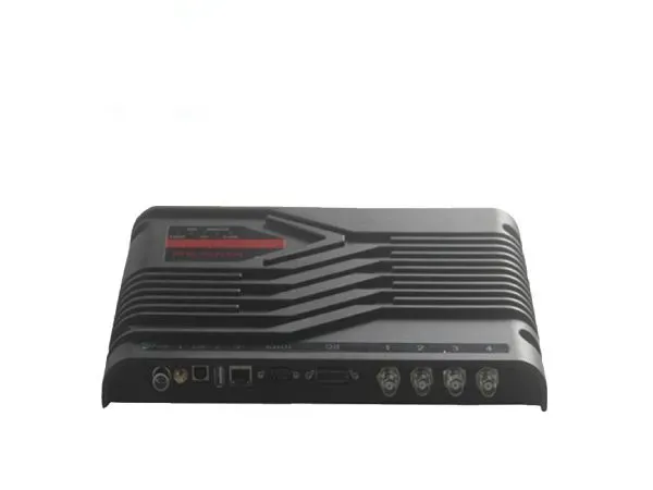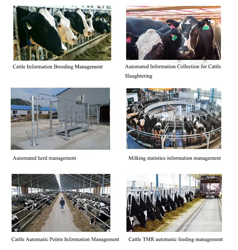


Features:
※Completely independent intellectual property design
※Designed based on Impinj R2000 reading and writing engine
※ Fully supports electronic labels that comply with EPC CLASS1 G2 and ISO18000-6B standards
※Working frequency 860~868MHz/902~928MHz (can be adjusted according to the requirements of different countries or regions)
※Works in broad spectrum frequency hopping (FHSS) or fixed frequency transmission mode
※Output power reaches 30dBm (adjustable)
※4 external TNC antenna interfaces, supporting automatic antenna fine-tuning and antenna failure detection
※Supports multiple working modes such as active, response, trigger, real-time query, etc.
※Supports internal 800 tag cache (EPC length 496 bits)
※Supports two anti-collision modes, EPC and TID
※Low power consumption design, single +9V power supply
※Supports RS232, RJ45 (TCPIP), WiFi (optional) and other communication interfaces, and optional POE network power supply
※Highly reliable design to meet harsh working environment requirements
※Supports Firmware online upgrade, and can customize the embedded WinCE or Linux operating system version.
Limit parameters:
| project | symbol | numerical value | unit |
| voltage | VCC | 16 | V |
| Operating temperature | TOPR | -10~+60 | ℃ |
| storage temperature | TSTR | -20~+75 | ℃ |
Specification:Unless otherwise specified, the specifications shown are taken under the operating conditions of TA=25℃ and VCC=+9V
| Project | Symbol | Small | Typical | Unit | |
| Voltage | VCC | 8 | 9 | 12 | V |
| Working current | IC | 800 | 1500 | mA | |
| Working frequency | FREQ | 902 | 928 | MHz | |
| Size | Size | 310x210x41 | mm |

1.Power interface J1
| Serial number | Symbol | Describe |
| 2 | PWR | +9V power supply |
| 4 | GND | land |
| 1,3 | NC | reserve |
2.WiFi antenna interface J2 (SMA Female)
3.USB interface J3 (Slave)
4.USB interface J4 (reserved)
5.RJ45 network interface J5
6.RS232 serial communication interface J6 (DB9 Femalee)
| Serial number | Symbol | Describe |
| 1 | NC | Reserved |
| 2 | TXD | Serial communication data input terminal |
| 3 | RXD | Serial communication data input terminal |
| 4 | NC | Reserved |
| 5 | GND | Land |
| 6 | NC | Reserved |
| 7 | NC | Reserved |
| 8 | NC | Reserved |
| 9 | NC | Reserved |
7. General input and output interface GPIO J7 (DB15 Female)
| Serial number | Symbol | Describe |
| 1 | Output1 | Universal output port 1 |
| 2 | Output2 | Universal output port 2 |
| 3 | Output3 | Universal output port 3 |
| 4 | Output4 | Universal output port 4 |
| 5 | Input1 | Universal input port 1 (internally pulled down to ground through a 47K resistor) |
| 6 | Input2 | Universal input port 2 (internally pulled down to ground through a 47K resistor) |
| 7 | Input3 | Universal input port 3 (internally pulled down to ground through a 47K resistor) |
| 8 | Input4 | Universal input port 4 (internally pulled down to ground through a 47K resistor) |
| 9 | TGIN | Trigger input (internally pulled up to +5V through a 10k resistor) |
| 10 | R+ | RS485 interface R+ terminal |
| 11 | R- | RS485 interface R-side |
| 12 | GND | signal ground |
| 13 | NC | Built-in relay normally closed terminal |
| 14 | NO | Built-in relay normally open |
| 15 | CM | Built-in relay common terminal |
8.TNC antenna 1-4 interface J8~J11

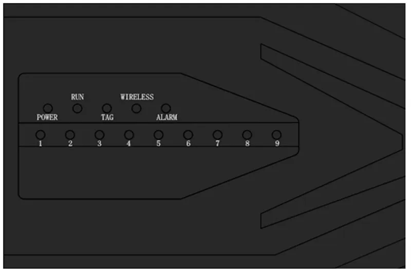
9.Indicator light
| Serial number | Symbol | Describe |
| Power | POWER | Power indicator |
| Run | RUN | Instruction execution instructions |
| Tag | TAG | Tag detected indication |
| Wireless | WIRELESS | WiFi working instructions |
| Alarm | ALARM | Alarm indication |
| 1~9 | 1~9 | RSSI indication |


